When a robotic mower follows a lawn edge accurately on one pass but drifts toward a flower bed on the next, the problem is rarely the RTK specification alone. Trees, walls, antenna placement, and an unstable correction link can all reduce positioning quality.
This article explains the accuracy RTK GNSS can deliver, the conditions that affect it, and how live corrections improve position estimates. It also covers fixed and float status, repeatability tests, and the checks needed before trusting a mapped boundary, route, or control point.
How Accurate Can RTK GNSS Be?
Published accuracy is only a starting point. The receiver’s solution state, correction continuity, and test environment determine whether centimeter-level performance remains usable during actual work.
Under favorable conditions, a fixed RTK solution commonly supports about 1–3 cm horizontal accuracy. Vertical results are usually less precise, so height-sensitive work requires a wider tolerance and independent checks. A fixed status indicates that the receiver has resolved carrier-phase ambiguities; a float status indicates that the solution is still uncertain and should not be used for centimeter-critical decisions.
Treat the specification as a performance range, not a permanent reading. Check estimated error, correction age, satellite geometry, and status stability while the receiver is stationary and moving. Repeat a measurement at a known point after reinitializing the system. A setup is dependable only when several readings stay within the tolerance required by the boundary, route, or control point.
What Factors Affect RTK GNSS Accuracy?
RTK accuracy reflects several conditions working together. Evaluating them separately helps explain why the same receiver can remain precise in one area and vary in another.
Satellite Geometry and Multi-Constellation Coverage
Accuracy improves when satellites are spread across the sky rather than clustered in one direction. Multi-constellation tracking increases the chance of retaining useful geometry near houses, fences, trees, and slopes. Review dilution of precision or the receiver’s quality indicator when available; a high satellite count with poor geometry can still produce a weak solution. Test the same point at different times if the sky view changes as satellites move.
Obstructions, Multipath, and Signal Interference
Trees, walls, metal roofs, parked vehicles, and retaining walls can block direct signals or reflect them before they reach the antenna. These reflected paths, called multipath, shift the calculated position even when the receiver remains connected. Inspect the operating area from antenna height, then repeat passes beside the strongest obstructions. Consistent drift in the same zone indicates a site limitation that may need a different antenna position or hybrid navigation support.
Baseline Distance and Correction Quality
RTK corrections may come from a local base, a network, or an integrated service. Longer separation from the reference can increase differences in atmospheric conditions, while high latency or interrupted delivery prevents the rover from applying corrections consistently. Monitor correction age, connection quality, and status changes during the full route. A short dropout may be recoverable; repeated dropouts make repeatability more important than the best accuracy number shown.
Receiver, Antenna, and Installation Setup
Mount the antenna level, rigid, and clear of shielding from the machine body or nearby metal. Loose brackets, vibration, cable problems, and an incorrect antenna offset can create errors that resemble poor satellite reception. Test first in an open area. If repeated measurements still spread widely there, inspect mounting, firmware, antenna configuration, and correction settings before evaluating the more obstructed parts of the site.
How Do RTK Corrections Improve Positioning Accuracy?
RTK improves a position only when clean satellite measurements, timely correction data, and a stable solution remain available while the receiver or machine is moving.
- Reference error detection: A base station or correction network with known coordinates identifies shared satellite orbit, clock, and atmospheric errors. The rover applies those differences instead of relying only on its standalone estimate.
- Carrier-phase resolution: A fixed solution means integer ambiguities have been resolved well enough for centimeter-level work. A float solution is still calculating them, so boundaries or control points should not be accepted yet.
- Correction continuity: Radio, cellular, or network delivery must remain timely. Watch correction age, fix status, and estimated error; repeated status changes indicate that the data link needs attention before measurement continues.
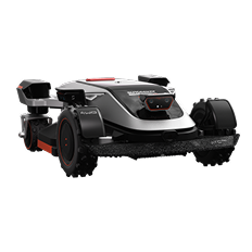
- Support during movement: Automated equipment needs stable positioning across the full route, not only at one test point. The Sunseeker Elite X9 robotic mower uses AONavi 2.0 with nRTK and VSLAM 2.0 to support boundary tracking and planned paths as site conditions change.
How Should You Judge Accuracy for Your Application?
A useful accuracy test compares repeatability with the allowable error of the task. These checks show whether the system can hold that standard throughout the working area.
- Define the tolerance: Set the maximum acceptable error before testing. A lawn boundary beside a flower bed may allow only a few centimeters, while rough mapping can accept a wider range.
- Confirm the quality state: Record only measurements made with a fixed solution, current corrections, and a stable estimated error. Mixing fixed and float readings hides the condition that caused the spread.
- Repeat a known point: Measure the same marked point at least five times, including after reinitializing the receiver. Compare the full spread, not just the average, to see whether the position can be reproduced.
- Test the difficult zones: Repeat the route near trees, walls, slopes, and narrow passages. A system is ready for automation only when the results remain within tolerance in the places where signal quality is weakest.
Conclusion
RTK GNSS accuracy varies with satellite geometry, correction quality, antenna placement, and surrounding obstacles. A fixed solution may achieve about 1–3 cm horizontal accuracy under stable conditions. In applications such as a robot lawn mower, this positioning supports more consistent movement along mapped routes and boundaries. Verify performance at known reference points and in narrow or partially obstructed areas. If results widen, check correction latency, receiver status, mounting, and sky visibility before changing the map.
FAQs
What is the accuracy of a fixed RTK solution?
Under favorable conditions, a fixed RTK solution commonly provides about 1–3 cm horizontal accuracy. Vertical accuracy is usually weaker, so elevation work needs a wider tolerance. Confirm that corrections are current, the antenna has a clear sky view, and repeated measurements return within the required range before treating the result as centimeter-grade.
What does a float status mean for RTK accuracy?
A float status means the receiver has not fully resolved carrier-phase ambiguities. The position may still be useful for general navigation, but its error is larger and less repeatable than a fixed solution. Check correction age, satellite geometry, obstructions, and the data link, then wait for a stable fixed status before recording centimeter-critical points.
How do trees and walls affect RTK GNSS accuracy?
Trees and walls can block direct satellite signals or reflect them toward the antenna, creating multipath error. Wet foliage, metal sheds, and narrow spaces often increase the effect. Test repeated passes beside each obstruction, compare the spread with an open-sky area, and use a better antenna position or hybrid navigation support where the required tolerance is not maintained.









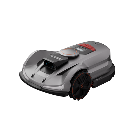 X7 / X7 Plus Gen 2High-performance mowing for lawns up to 1.5 Acres.USD 2499 / USD 2999
 Learn More
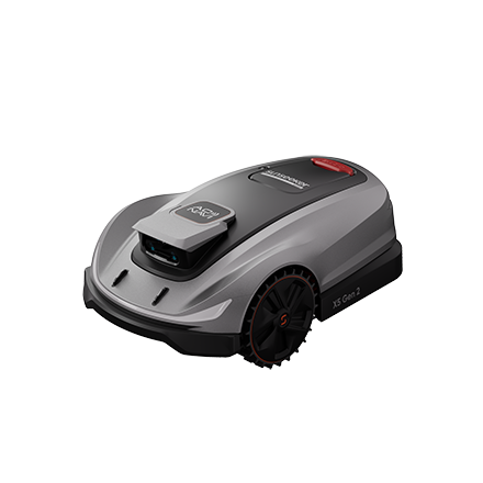 X5 Gen 2Powerful and versatile, for lawns up to 0.5 Acre.USD 1999
 Learn More
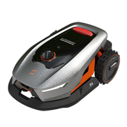 X4Smart LiDAR mower built for effortless, boundary-free lawn care.USD 1399
 Learn More
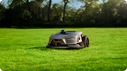
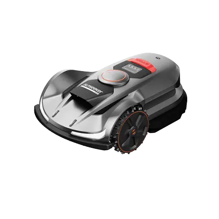 X7 / X7 Plus / X7 ProPower Through Every Slope.
 Learn More
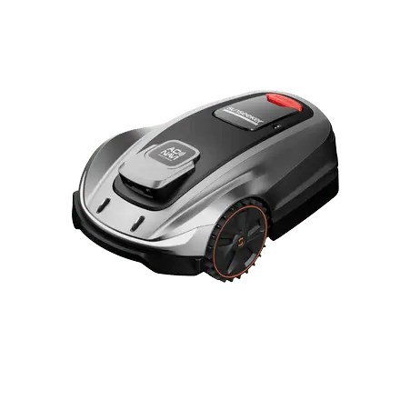 X5Smart Vision. Effortless Mowing
 Learn More