iToF estimates depth by comparing the phase of emitted and reflected modulated infrared light. It can create dense depth maps at useful frame rates, but accuracy is shaped by multipath, ambient light, reflectivity, motion, modulation choices, and calibration. It is widely used in 3D cameras, proximity sensing, and robotic perception.
A depth camera may look accurate indoors and then become noisy beside a bright window or on a glossy surface. That change is often tied to how the sensor interprets returning infrared light rather than a simple “range” limit. iToF is common in compact 3D sensing because it can estimate depth across many pixels at once. This guide follows the measurement process, the main accuracy limits, the difference from dToF, and the applications where phase-based depth is especially useful.
What Is iToF?
iToF is easiest to understand as a phase-based depth method rather than a generic time-of-flight label. Its core idea is simple once the emitted and returned light signals are viewed together.
Indirect Time-of-Flight, or iToF, is an active depth-sensing technique that estimates distance from the phase delay between emitted and reflected modulated infrared light. Unlike a conventional RGB camera, which records color and brightness, an iToF sensor is designed to estimate how far surfaces are from the camera. The “indirect” name distinguishes phase-based timing from direct ToF systems that time individual light pulses or photon arrivals. iToF is especially useful when an application wants a dense depth image across a field of view, such as a 3D camera, gesture sensor, or robotic perception module.
How Does iToF Measure Distance?
iToF turns a phase shift in modulated light into a distance estimate. Following that measurement path makes the underlying ranging logic easier to understand.
Modulated Infrared Light
An iToF sensor illuminates a scene with infrared light whose intensity is modulated at a known frequency. The light reflects from objects and returns to the receiver with the same general modulation pattern, but shifted in phase because it spent time traveling to the object and back. The sensor does not need to identify a single emitted pulse. Instead, it compares the transmitted and received waveforms over many cycles. That makes the measurement well suited to compact depth cameras that need a dense field of distance values rather than one long-range point measurement.
Phase Shift and Distance Calculation
The key measurement in iToF is phase difference. If the returned modulation is delayed by a fraction of one cycle, the electronics convert that phase offset into a round-trip propagation time and then into distance using the speed of light. Because phase repeats every full cycle, a single modulation frequency has an unambiguous distance limit. Practical sensors may use multiple frequencies or coded modulation to extend usable range and reduce ambiguity. The calculation is performed for many pixels at once, which is why iToF can produce depth at video-like frame rates.
Depth Map Generation
Each photosensitive pixel or pixel group estimates a distance, producing an array of depth values aligned with the scene. After calibration, filtering, confidence checks, and invalid-pixel handling, the device turns those measurements into a depth map. A depth map can be displayed as a grayscale image, converted into a 3D point cloud, or fused with a conventional camera image. The important distinction is that it represents geometry: nearby surfaces receive smaller distance values and farther surfaces larger values, giving software a direct way to reason about shape and separation.
What Affects iToF Accuracy?
Real-world performance depends on the quality of the signal reaching the sensor and on how cleanly the system can interpret it. The points below explain the main conditions that shape reliable measurements.
Multipath Interference
Multipath occurs when emitted light reaches a pixel after reflecting along more than one path. A wall near a shiny floor, a corner, or a partially reflective object can mix an early return with a delayed return. The measured phase becomes a blend instead of representing one clean distance, so edges and concave spaces may appear warped. Better optics, modulation schemes, confidence metrics, scene filtering, and multi-frequency processing can reduce the error, but system designers still need to test the sensor in the geometry and materials expected in the final application.
Ambient Light and Signal-to-Noise Ratio
Sunlight and strong indoor illumination add photons that did not come from the sensor emitter. That background raises noise and can reduce the contrast of the modulated return, especially at longer distances or on dark surfaces. The result may be noisier depth, lower confidence, or missing pixels. Optical filters centered on the emitter wavelength, higher modulation contrast, appropriate exposure, and temporal averaging can help. Outdoor designs should be evaluated in direct sun rather than only in a lab, because signal-to-noise ratio can change dramatically between those environments.
Reflective and Low-Reflectivity Surfaces
Very dark materials return little infrared energy, while glossy or mirror-like materials can direct energy away from the receiver or create strong specular reflections. Both cases can distort a depth image. Black fabric may produce weak or invalid pixels; polished metal or glass may create unstable distances depending on angle. A robust system uses confidence thresholds and often combines depth with other sensing cues. Mechanical placement also matters: changing the camera angle can turn a difficult reflection into a usable diffuse return without changing the sensor itself.
Motion Artifacts and Calibration
Depth is only useful when the optics, timing, and geometry are calibrated. Temperature changes, lens distortion, pixel timing offsets, and emitter-receiver alignment can introduce systematic error if left uncompensated. Motion adds another challenge because a scene may change during the sequence of phase samples used for one depth frame. Fast-moving edges can therefore show transient artifacts. Factory calibration provides a baseline, while application-level validation checks whether mounting vibration, temperature range, exposure settings, and frame rate are suitable for the expected motion.
How Does iToF Compare with dToF?
The two approaches solve related problems in different ways, so the practical trade-offs become clearer when the same performance factors are viewed side by side.
Factor | iToF | dToF |
Primary measurement | Phase shift of modulated light | Direct pulse/photon travel time |
Typical strength | Dense depth imaging | Longer unambiguous ranging |
Common challenge | Phase ambiguity and multipath | Timing precision and photon statistics |
Ambient light | Can reduce modulation SNR | Can increase background photon rate |
Architecture | Correlation/phase pixels | Fast detector and timing circuitry |
Where Is iToF Used?
The technology becomes easier to understand when it is tied to the jobs it performs in real systems. These examples show how the same underlying measurement can support different kinds of automation.
Depth Cameras and 3D Sensing
In a depth camera, iToF can capture a dense distance image without relying on visible texture. That supports room-scale geometry, people segmentation, volume estimation, background separation, and 3D reconstruction. The sensor can work alongside an RGB camera when color and geometry are both needed. Its useful range depends on modulation, optics, emitter power, surface reflectivity, and ambient light, so “3D camera” is not a guarantee of identical performance in every scene. Matching field of view and depth range to the task is more important than raw pixel count alone.
Robotics and Obstacle Detection
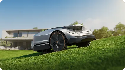
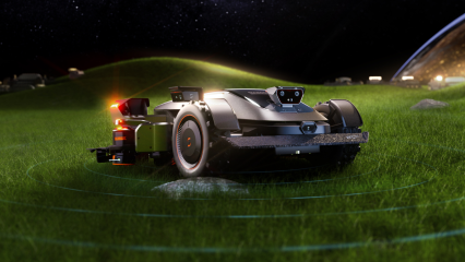
A robot can use a depth map to identify free space, estimate object distance, and decide whether a passage is wide enough to traverse. Unlike a single proximity sensor, a depth camera provides spatial structure across many pixels, which helps separate the ground from obstacles and estimate their shape. Outdoor robots often fuse depth with vision, inertial sensing, wheel odometry, or satellite positioning because no single sensor is ideal in every condition. For lawn automation, this layered approach can support safer routing around furniture, trees, borders, pets, and changing yard objects.
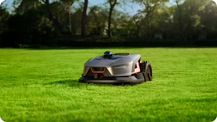
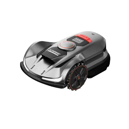
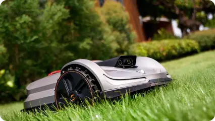
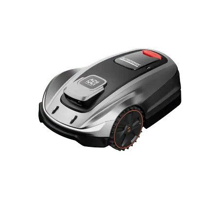
For a current Sunseeker example, Sunseeker Elite X9 combines binocular vision, iToF and dToF sensors with infrared sensing for 360-degree obstacle detection.
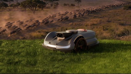
For a practical outdoor robotics category, see Sunseeker’s robot lawn mower collection, where navigation and obstacle sensing are combined with autonomous mowing.
AR, Gesture, and Proximity Sensing
Short- and medium-range depth data is useful wherever software must understand how far a hand, face, or surface sits from a device. Gesture systems can isolate hands from the background and track motion in 3D. AR systems can improve occlusion, scene meshing, and object placement when reliable depth is available. Proximity functions can detect approach or presence without requiring detailed color imagery. The engineering trade-off is usually between depth range, field of view, power, frame rate, package size, and the amount of ambient light in the intended environment.
Conclusion
iToF turns phase delay in modulated infrared light into dense depth information, but its useful accuracy depends on signal quality, reflectivity, motion, multipath, and calibration. Reading those limits alongside range and resolution gives a much clearer picture than treating every time-of-flight sensor as equivalent. In robotics, depth sensing is most effective when it complements the navigation stack and the operating environment.
FAQs
What is 3D iToF and how does the 3D iToF sensor work?
3D iToF uses modulated infrared illumination and measures the phase delay of the reflected signal across many sensor pixels. Each pixel converts that phase difference into a distance estimate, and the camera combines the measurements into a depth map. Calibration, modulation frequency, reflectivity, ambient light, and motion all influence the final depth confidence.
What is a 3D iToF camera?
A 3D iToF camera integrates an infrared emitter, phase-sensitive image sensor, optics, timing electronics, calibration data, and depth processing. Instead of returning only color, it produces a depth value for many points in the scene. Some modules also provide amplitude, confidence, or synchronized RGB data for combined appearance and geometry.
What is the benefit of a 3D iToF sensor?
Its main advantage is dense depth measurement in a compact camera format at practical frame rates. That can simplify 3D segmentation, proximity sensing, gesture tracking, robot perception, and scene reconstruction. The application still needs the right range and lighting margin because sunlight, multipath, weak reflectivity, and motion can reduce measurement confidence.



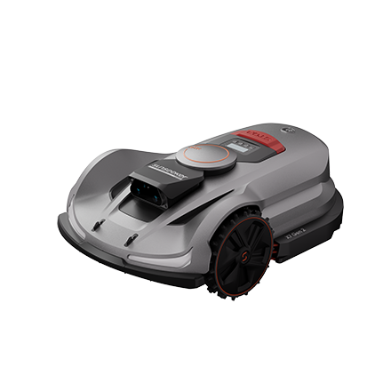
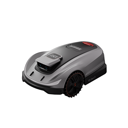

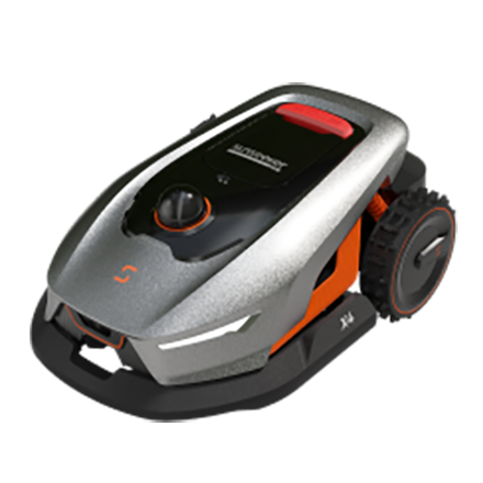
 X7 / X7 Plus Gen 2High-performance mowing for lawns up to 1.5 Acres.USD 2499 / USD 2999