dToF measures light travel time directly, while iToF infers distance from phase shift. dToF often suits longer unambiguous range; iToF often suits dense close- to medium-range depth. The better choice depends on sunlight, reflectivity, frame rate, depth resolution, power, optics, and total system cost.
Two time-of-flight sensors can both report depth yet behave very differently at long range, in bright light, or around reflective objects. The reason is that dToF times returning light directly, while iToF interprets phase shift in a modulated signal. Those architectures lead to different trade-offs in range, depth resolution, multipath behavior, cost, and integration. The comparison below focuses on what changes in practice so you can match the sensing method to the environment instead of choosing from the acronym alone.
What Is dToF?
dToF starts with a direct timing question: how long does a light pulse take to travel to the target and return? That timing model sets up the comparison with phase-based iToF.
Direct Time-of-Flight, or dToF, sends short light pulses and measures how long reflected photons take to return. Distance is derived from the round-trip travel time of light. Depending on the design, a dToF sensor may use fast photodiodes, SPAD arrays, timing counters, or photon histograms to estimate the return. Because the measurement is time based rather than phase based, it can support long unambiguous ranges. Actual performance still depends on emitter power, eye-safety limits, detector sensitivity, timing resolution, target reflectivity, optics, and background light.
What Is iToF?
iToF estimates the same physical quantity through a different signal relationship. The distinction becomes clear when phase delay is translated into distance.
Indirect Time-of-Flight, or iToF, illuminates the scene with intensity-modulated infrared light and measures the phase shift of the returned modulation. The phase delay represents a fraction of the modulation period, which can be converted into propagation time and then distance. Many pixels perform this measurement in parallel, producing a dense depth image. Because phase repeats every cycle, a single frequency has an ambiguity distance; practical systems may use multiple modulation frequencies or codes to extend useful range. iToF is therefore often attractive for compact 3D cameras and close- to medium-range scene sensing.
What Are the Key Differences Between dToF and iToF?
The two approaches solve related problems in different ways, so the practical trade-offs become clearer when the same performance factors are viewed side by side.
Factor | dToF | iToF |
Distance basis | Pulse/photon time-of-flight | Modulation phase shift |
Range tendency | Often stronger at longer range | Often optimized for close/medium dense depth |
Depth output | Point, zone, or array depending on sensor | Dense depth array is common |
Multipath | Can sometimes separate delayed returns | Mixed paths can bias phase |
System trade-off | Fast timing/detector complexity | Modulation, ambiguity, correlation processing |
Measurement Range
dToF measures the travel time of light pulses directly, so it is naturally suited to longer unambiguous ranges when the timing electronics and optical power support them. iToF derives distance from phase, which is efficient for dense depth but introduces a periodic ambiguity tied to modulation frequency. Multi-frequency iToF can extend range, while high-performance dToF arrays can still be limited by eye-safety power, detector sensitivity, and background light. A range specification should therefore be read together with target reflectivity and lighting conditions, not as a universal maximum.
Depth Resolution
iToF is commonly attractive for smooth, dense depth images because each pixel estimates phase continuously across a scene. dToF resolution depends on timing precision, detector design, histogram processing, and photon statistics. Neither label alone determines the final millimeter or centimeter performance. At close range, a well-designed iToF camera may provide very stable relative depth; at longer range, a dToF system may preserve useful separation where phase-based signal quality has fallen. The correct comparison is at the distance, field of view, and frame rate the application actually uses.
Ambient Light Performance
Bright ambient light competes with the active infrared signal in both architectures. dToF systems can reject some background by looking for photons in narrow time windows, while iToF systems use correlation with the modulation waveform to distinguish the active signal. In strong sunlight, detector saturation, optical filtering, emitter wavelength, integration time, and target reflectivity all matter. Outdoor performance should be judged from measured depth confidence in direct sun and shade transitions, because an architecture that looks strong in indoor specifications may behave differently on reflective grass, pavement, or vehicles.
Multipath Susceptibility
iToF can be notably sensitive to mixed light paths because phase measurements from multiple reflections combine at a pixel. dToF can sometimes separate returns in time when the paths are far enough apart, although close or weak secondary returns can still complicate interpretation. Corners, glass, glossy floors, and narrow spaces are common stress cases. If multipath is critical, test the complete optical stack and processing pipeline with representative scenes instead of assuming one ToF category automatically eliminates the problem.
Sensor Architecture and Cost
dToF often relies on fast emitters, sensitive single-photon or avalanche detectors, and precise timing circuitry. iToF uses modulated illumination and correlation-capable pixels, which can be efficient for dense depth imaging. Cost depends heavily on sensor size, optics, laser or LED power, processing, calibration, and production volume, so architecture is only one part of the bill of materials. A lower-cost sensor that needs expensive optics or heavy processing may not reduce system cost. Power and thermal design should be compared at the same range and frame-rate target.
Which Method Fits Different Applications?
The technology becomes easier to understand when it is tied to the jobs it performs in real systems. These examples show how the same underlying measurement can support different kinds of automation.
Outdoor Robotics and Long-Range Sensing
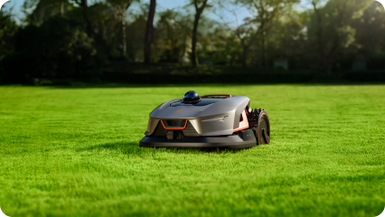
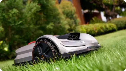
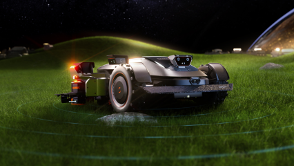
Outdoor robots need measurements that remain useful over changing light, long sight lines, and mixed reflectivity. dToF can be a strong fit when longer-range ranging or separation of time-domain returns is important. A robot may still combine it with cameras, GNSS, inertial sensing, wheel odometry, or LiDAR because navigation requires more than distance alone. In a robot lawn mower, the useful design question is not only “how far can it see?” but also how consistently the entire perception stack can maintain boundaries, recognize obstacles, and recover when one signal becomes weak.
For a current Sunseeker example, Sunseeker Elite X9 uses dToF sensors as part of its obstacle-detection system. These depth-sensing technologies work with the mower’s vision system to measure distance and detect obstacles more accurately, helping the X9 navigate complex lawn environments with greater awareness.
For a current outdoor application, browse the robot lawn mower category and compare how positioning is fused with local perception.
Indoor Depth Cameras and Close-Range 3D Imaging
Indoor depth cameras often prioritize dense geometry, compact size, moderate range, and consistent frame rate. iToF fits many of these requirements because phase can be estimated across a pixel array and converted into a full depth image. Controlled lighting also reduces one of the most difficult outdoor variables. Typical uses include body tracking, room scanning, object dimensioning, and robot navigation. The selection still depends on minimum distance, field of view, surface properties, and motion; a camera optimized for people at two meters may not be ideal for precision inspection at twenty centimeters.
Consumer Devices and Embedded Systems
Embedded products place strong constraints on power, heat, package size, compute, and calibration time. iToF can provide a convenient dense depth stream, while dToF can be attractive for compact ranging modules or applications that need stronger long-range behavior. Designers should compare total system power at the required frame rate, the processor load for filtering, and the calibration process needed on the production line. The best choice is the one that meets the depth-confidence target inside the device’s thermal and cost envelope, not the one with the most impressive standalone sensor specification.
Conclusion
The central dtof vs itof difference is how distance is inferred: direct photon travel time versus phase shift in modulated light. That choice affects range, depth density, ambient-light behavior, multipath sensitivity, hardware complexity, and cost. Neither method wins every application, so the useful decision starts with measurable range and scene requirements. Outdoor robots often combine depth or perception sensing with a separate positioning layer, an approach also reflected across Sunseeker’s autonomous mower platforms.
FAQs
What is the difference between iToF and dToF?
iToF estimates distance from the phase shift of modulated light, while dToF measures the travel time of emitted light pulses or photon arrivals more directly. iToF is often used for dense depth imaging; dToF can be attractive for longer unambiguous range. Actual accuracy depends on the full sensor design and environment.
Which is better for laser measurement, iToF or dToF?
Neither is universally better. dToF is often preferred when long-range timing and time-domain return separation are important. iToF is often a strong choice for dense close- to medium-range depth cameras. Compare the required range, frame rate, sunlight exposure, target reflectivity, power, and depth confidence before choosing.
What are the advantages and disadvantages of iToF and dToF?
iToF can deliver dense depth efficiently, but phase ambiguity and multipath can be important limitations. dToF can support longer unambiguous range and time-resolved returns, but fast detectors and timing electronics may add complexity. Both can be affected by sunlight, reflectivity, optics, calibration, and signal-to-noise ratio.



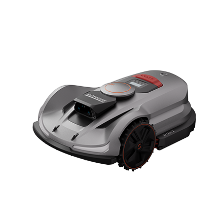
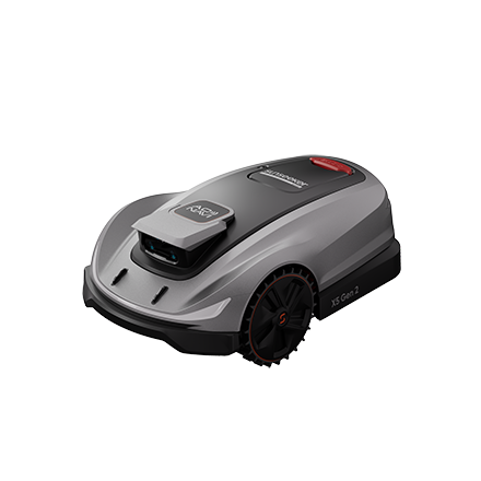

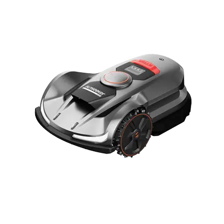
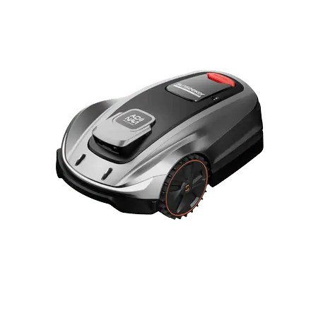

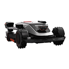




 X7 / X7 Plus Gen 2High-performance mowing for lawns up to 1.5 Acres.USD 2499 / USD 2999